Ezcad3 Upgrade
This will document the process of my upgrade from Ezcad2 to Ezcad3 on my 60w M7 MOPA .
*This will be updated as I notice mistakes, find more photos or have more information to add.*
Original link for this post: https://docs.google.com
___________________________________________________________________
BoM
- Ezcad3 controller (dlc2-m4-2d in my case)
- 12v 3A Meanwell power supply
- Extra wire
- Barrel connectors
- Z AXIS parts
- Nema 23 stepper motor
- Nema 23 motor mount
- Dm542ma step driver (or equivalent)
- Shaft coupler
- End stop switch (if you want axis homing)
- Extra wire
- Connector (for interfacing the case)
- M5x0.8 65mm pitch screw
- M5x0.8 drill and tap
- Wire shrink tube
- Wire sheathing
Tools
- Wire strippers
- Soldering iron
- Multimeter (if you want to check pins for sanity)
- Wire crimper (open barrel)
- Drill & Tap set
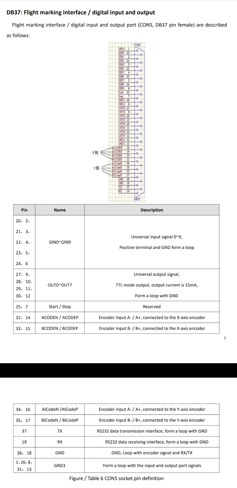
Pinouts for Reference
LMCV4-FIBER-M (ezcad2 controller)


________________________________________________________________
DLC2-M4-2D (ezcad3 2D controller)
-
DLC2 (DSP Laser Control)


-
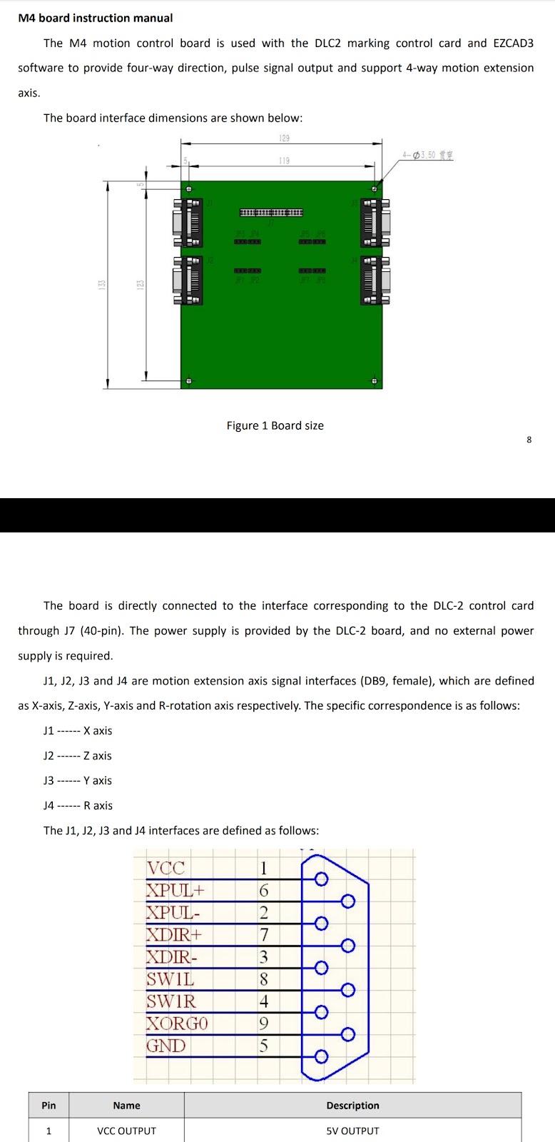
M4 (Motion Controller)
________________________________________________________________
Removing the Old controller
Removal of the old ezcad2 controller should be fairly straightforward. Make sure you disconnect the power for the laser at the wall outlet.
For split units
- Disconnect the main power to the machine
- Remove the top bolts of the laser case, typically 3 on the front and 3 on the back


- Lift off the top of the case.
- Lift/slide the Sides out and this should open up both sides of the unit exposing the laser source on one side of the(typically the right side) & The power supplies and or step drivers on the other.(normally on the right )

- Find the LMC Controller. This is typically located on the top portion of the case.

- Disconnect the various Db Connectors as well as the USB from the LMC controller, we will reuse all of these but one on the new DLC controller. The one we will rewire is connector #4 in the seen in the LMC pinout reference
- Unbolt and remove the LMC controller

________________________________________________________________
Installing the new power supply
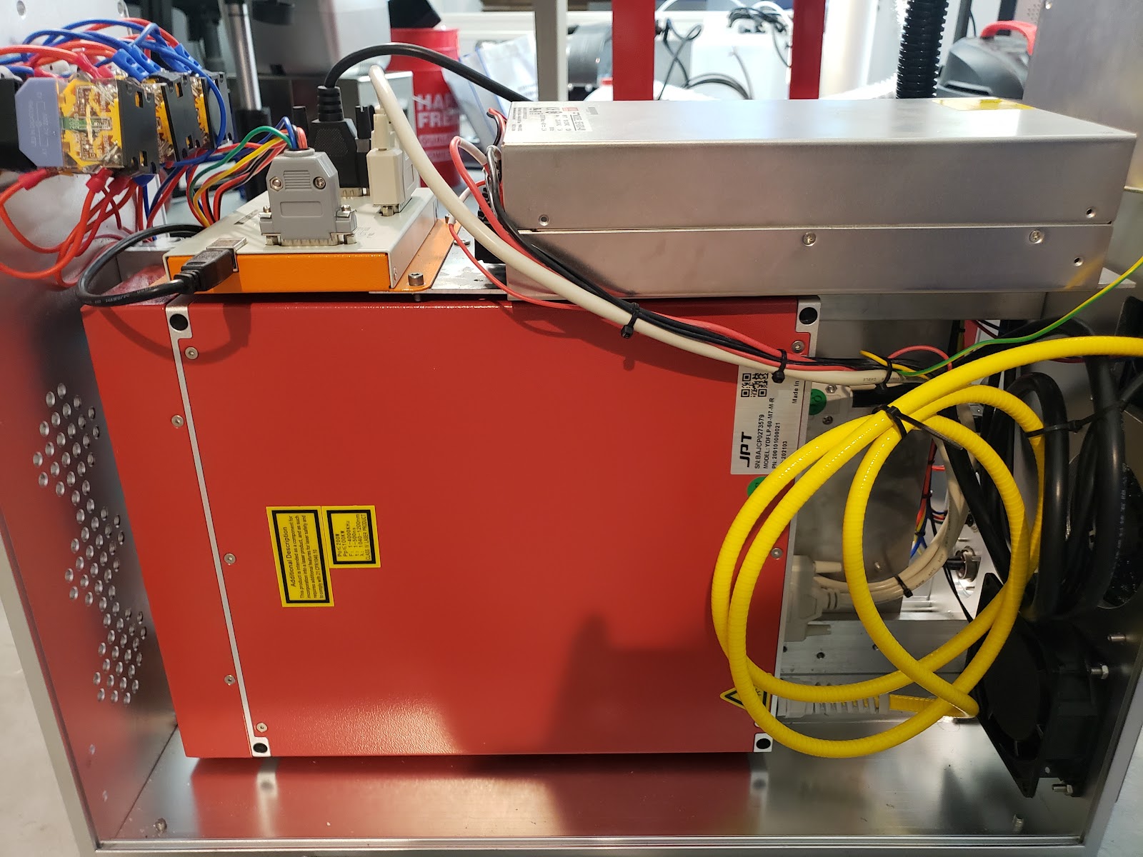
- Locate the old controllers 5v Power supply, This will typically be a small power supply found on the Left side of the machine. This is mine..

- Check wiring if any auxiliary equipment is attached to the old 5v power supply. If auxiliary equipment is in place please check that it is compatible with the new 12v power supply.
- Label any wiring that you plan to disconnect
- Unbolt and remove the old power supply,


- Now test fit the new 12v 3a power supply, if you are unable to match the old mounting holes you will need to drill and tap new ones to work for the new power supply.
- Mount your new power supply

________________________________________________________________
Installing the DLC-M4-2D
-Find the best location for your new Ezcad3 controller, These things are big so make sure you leave clearance for the connectors.
My machine had a fairly small case so I couldn’t fit the DLC controller where the old LMC controller used to live without getting closer than I’d like to the mains power and the 48v power supply meant for the laser source… I scouted a place that seemed like it would work well and started designing a mount.
(Left- Controller is too close to both the mains and the 48v power supply for the laser source, Right- This is where i have decided to mount the new controller )


This is the mounting bracket I designed in Illustrator & the final cut fresh off the laser.


Now that it’s mounted the old Laser control and Galvo control along with the Power wires from our new 12v power supply can be connected to the controller. See DLC pinout reference

________________________________________________________________
Wiring the Motor Controls

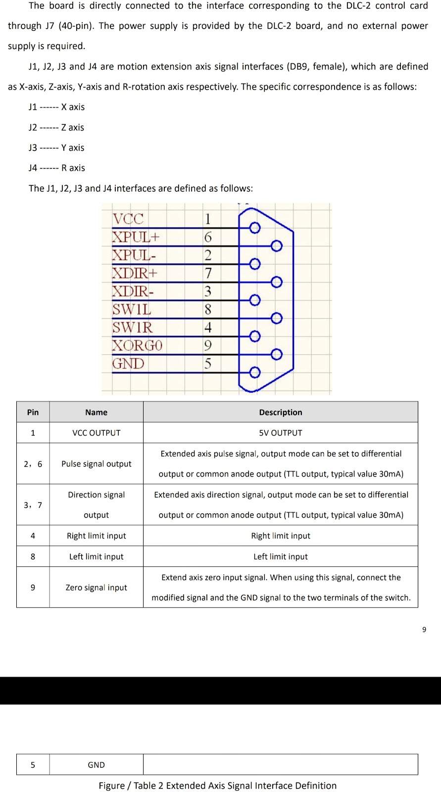
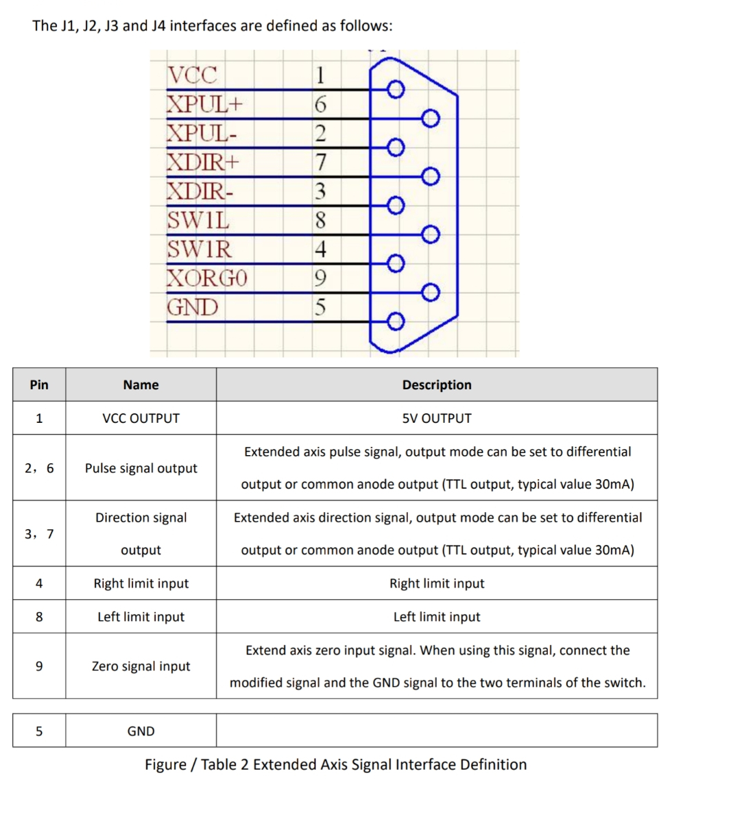
This is the Pinout of the DB9 Motor connector on the DLC-M-2D Controller
Here I labeled & connected my wiring to the Pulse and Direction pins(labeled on the driver) of the DQ542MA Step driver connector(green). For this I used open barrel crimp terminations and then inserted those into the connector screw port and tightened the screws onto the barrel terminations.
Now that we have that out of the way we can connect the other side of our wiring to the Db9 connector included with the Ezcad3 DLC board. We will connect PUL + to pin 6, PUL – to pin 2, DIR + to pin 7 & DIR – to pin 3. (See images below)
If you plan to use a home switch you will need to wire that here as well, I didn’t but i may add one in the future.. See the reference pinout
Note: The connection on the included db9 connector is a solder cup so you will need a soldering iron, be sure to slide on your shrink tube before soldering the connection. After making the connection slide the heat shrink tube down and apply heat to securely cover the solder joint and any exposed wire.


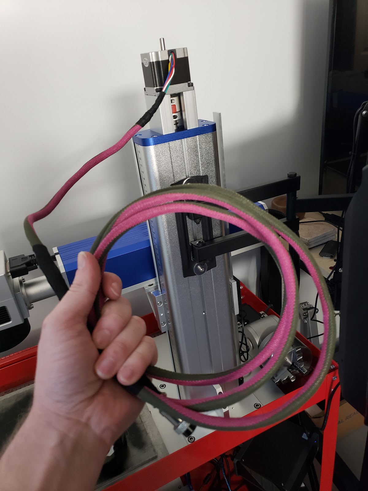
Now that it’s all wired up I added some sheathing and black harness tape to make things look a little more tidy.

Add the included Db9 Cover and plug your new motor wiring into your Step Driver and the DLC motor axis (The picture below is of the Z axis)


Repeat this for each axis you need control over…. Rotary anybody ?
Z Axis Motor Installation


The Parts arrive and we get a quick mock up.


Now the end cap of the Z axis is removed and brought to be scanned along with the Nema 23 Mounting block. For this I just used a common photocopier to scan accurately sized reference photos for making cutting templates on the laser. These reference photos were brought into my vector software (Inkscape & illustrator) and traced to create an outline to help me line up the Z axis cap for cutting the drill guides. This was then exported for ezcad.
Once the guides were cut I drilled and tapped the holes to accept an M5x0.8 thread. The next thing that needed to be done was to modify the shaft coupler that is to go between the motor and the Z axis screw. My Z axis screw had an end diameter of 11.75mm with the motor having a shaft diameter of 6.35mm. The closest I could find was a shaft coupler to connect 6.35mm to 12mm so there will need to be a hole drilled and tapped on the 12mm side of the coupler for a set screw to lock it into place on the 11.75mm Z axis lift screw.
The motor was then attached using the NEMA 23 mounting block along with 4 M5x65mm socket cap bolts, The wires were then extended and soldered to the connector shown above.
|
|
|
|
|
|
|
|
|
|
|
|
|
|
|
|


___________________________________________________________________________
Setup & Calibration
Now that everything is installed and operating we need to calibrate the lens for our new ezcad3 install. For this we will use the Calibration Wizard 9 point correction.
Start by opening the calibration wizard

I will be using the 2D XY Correction, once selected click “Confirm/Exit”

This will bring us to the 9 point correction

From here we will confirm scanner param

On my machine setting Galvo 2 = X 


Once set click “Enter/Exit”, Make sure to place a large scrap piece on the bed then click “Mark Image(3*3)”. You should end up with something looking like the picture below

Now you’ll need to measure from point to point and input those values into the “Input coordinate” section of the calibration wizard. These should be measured like so..

This is the measuring order needed for each field, the red fields can be set to zero. You will want to be accurate with this so use some measuring calipers if you can.

This is what mine came out like (your values will likely be different).
Once you have filled all the fields Click “Build Cor File” followed by “Save Cor File”. We will point Ezcad3 to this file later.

Next we’ll pop open ezcad3 and enter the F3 params menu

Once in the F3 params menu we’ll set the field named “Use the correction file” to “True”

Then under the “File Name” field we will select the 9 point correction file we just made by clicking the button with the three dots.


Congratulations!! If everything was done correctly your lens should now be calibrated.